The structure and performance of optical fiber connectors
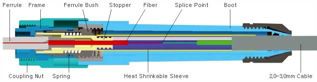
In this method, the optical fiber is inserted and fixed in the pin, and the surface of the pin is polished to achieve alignment in the coupling tube. The outer components of the pins are made of metal or non-metal materials. The butt end of the pin must be polished, and the other end usually uses a bending restriction member to support the optical fiber or optical fiber cable to relieve stress. Coupling tubes are generally made of two-half synthetic, fastened cylindrical members made of ceramic, bronze or other materials, and are often equipped with metal or plastic flanges to facilitate the installation and fixation of the connector. In order to align the optical fiber as accurately as possible, the processing precision of the pin and the coupling tube is very high.
Performance definition of optical fiber connector
The performance of optical fiber connectors is first of all optical performance. In addition, the interchangeability, repeatability, tensile strength, temperature, and plug-in times of optical fiber connectors must also be considered.(1) Optical performance: The requirements for the optical performance of optical fiber connectors are mainly the two most basic parameters of insertion loss and return loss.
Insertion Loss (InsertionLoss) is the connection loss. It refers to the loss of link effective optical power caused by the introduction of connectors. The smaller the insertion loss, the better, and the general requirement should be no more than 0.5dB.
Return Loss (ReturnLoss, ReflectionLoss): It refers to the ability of the connector to suppress the reflection of link optical power, and its typical value should not be less than 25dB. In the actual connector, the pin surface has been specially polished, which can make the return loss greater, generally not less than 45dB.
(2) Interchangeability and repeatability
Optical fiber connectors are universal passive components. For the same type of optical fiber connector, generally can be used in any combination, and can be used repeatedly, the additional loss introduced by this is generally within the range of less than 0.2dB.
(3) Tensile strength
For finished fiber optic connectors, the tensile strength is generally required to be no less than 90N.
(4) Temperature
Generally, the optical fiber connector must be able to be used normally at a temperature of -40oC~+70oC.
(5) Mating times
The optical fiber connectors used can basically be plugged and unplugged more than 1,000 times.
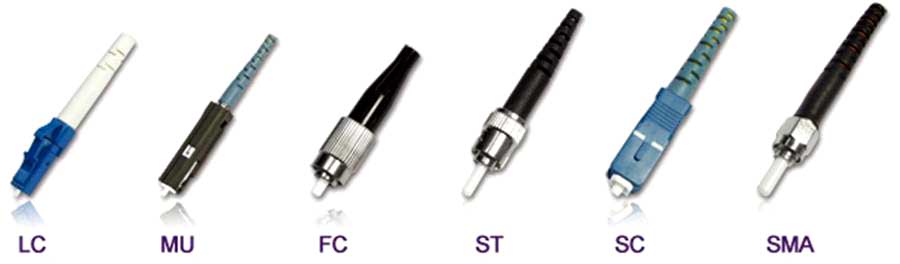
The part in front of the "/" indicates the connector model of the pigtail, and the description is described above. "/" indicates the cross-section process of the optical fiber connector, that is, the grinding method. There are three types of fiber connector end-face contact: PC, UPC, and APC. <Figure omitted> PC——Physic Contact, the original meaning is the meaning of physical contact, the end face of the pin body is the physical end face; UPC——Ultra Physical Contact, the end face of the pin body is the super physical end face; APC type-Angled Physical Contact, the end face of the pin body is an angled physical end face; In addition to the physical difference, the difference between the three is also the return loss, that is, the reflection loss (performance). There is no APC type for PC multimode fiber. "PC" is the most widely used in telecom operators' equipment, and its joint section is flat. The attenuation of "UPC" is smaller than that of "PC". It is generally used for equipment with special requirements. Some manufacturers use FC/UPC for internal jumpers of optical connection equipment, mainly to improve the equipment's own indicators. "APC" is mostly used in radio and television and early CATV systems. Because APC uses an end face with an inclination angle, it can improve the quality of the TV signal. The main reason is that the TV signal is analog light modulation. When the coupling surface of the joint is vertical, the reflected light returns along the original path. Because the non-uniformity of the fiber refractive index distribution will return to the coupling surface again, although the energy is small at this time, the noise cannot be completely eliminated due to the analog signal. So it is equivalent to superimposing a weak signal with time delay on the original clear signal, and the performance picture is ghosting. The inclination of the pigtail headband prevents the reflected light from returning along the original path. Generally, this problem does not exist with digital signals.
Connection steps of optical fiber connector
1. Optical fiber quick connector is a very innovative field termination connector. It contains factory-installed optical fibers, pre-polished ceramic ferrules, and a mechanical connection mechanism.
2. When terminating, only the incoming optical fiber or indoor optical fiber is inserted into the mechanical splicing mechanism, no other tools are needed, and the termination process only takes about 2 minutes, which greatly saves installation time.
3. The ferrule and end face of the optical fiber quick connector have been pre-polished and pre-polished before leaving the factory. The mechanical connection mechanism is located at the end of the ferrule to fix the inserted fiber.
4. The mechanical connection mechanism is mainly composed of V-groove and clamping elements;
When you need to insert an optical fiber, use a wedge clamp to open the V-groove to facilitate the smooth insertion of the optical fiber.
5. When the optical fiber is inserted into the V-shaped groove and fixed, just pull out the wedge clamp from the V-shaped groove.


