Main Specifications and Electrical & Mechanical Properties of RF Connectors
- PRODUCT DETAIL
The naming of the radio frequency coaxial connector consists of two parts: the main name code and the structure code, separated by a dash "-" in the middle. Main name code The main name code of the radio frequency connector adopts the internationally used main name code. The naming of different structural forms of specific products is specified in the detailed specification, and the structural form represents the structure of the radio frequency connector.
Example of model composition of RF connector
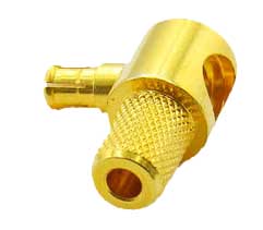
Example 1: MCX-JW3 RF connector
Represents MCX type curved radio frequency plug, the inner conductor of the plug is a pin contact, and it is equipped with SYV-50-3, RG-58/U and other radio frequency cables.
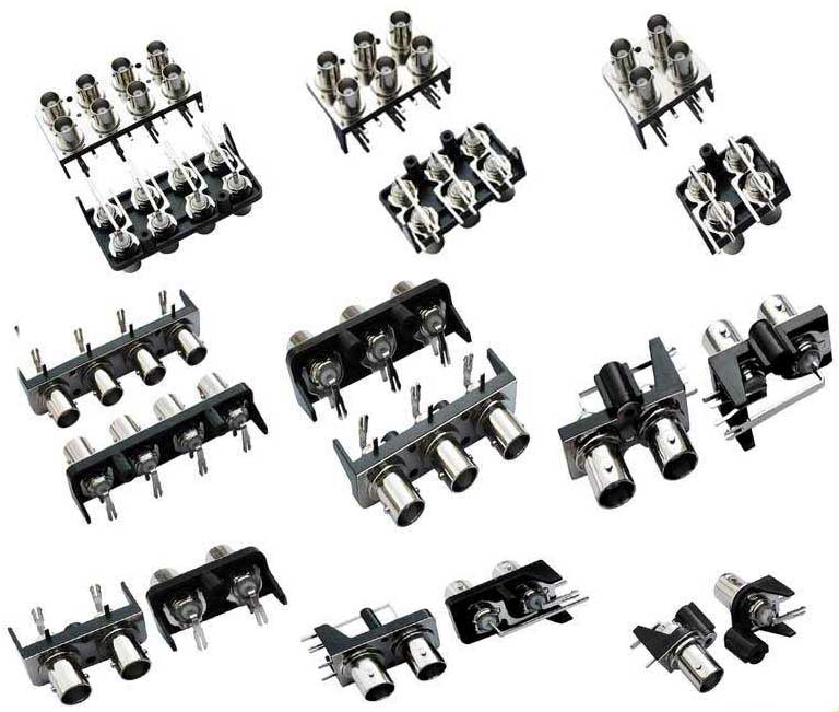
Example 2: BNC-KWE
It means that the BNC bend type welded on the printed circuit board is an RF socket with an impedance of 50Ω.
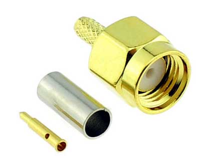
Example 3: SMA-C-J1.5
Indicates a SMA straight RF plug, the inner conductor is a pin contact, and it is equipped with SFF-50-1.5-1, RG-174/U and other RF cables. The termination form is crimp type.
● The model composition example of the adapter
The model of the adapter is derived based on the model of the plug or socket, and generally adopts the following forms:
The main code part of the adapter model is indicated by the main code of the connector (in-series adapter) or fractional type (inter-series adapter).
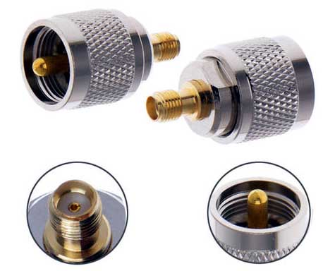
Example 1: SMA-50JK
Indicates the SMA type 50Ω series internal adapter, one end is male contact, and the other end is female contact.
Sample question: BNC/SMA-50JK
It means an adapter with a BNC male contact at one end and a female SMA contact at the other end with an impedance of 50Ω.
● Model composition example of impedance converter
Example: N-50J/75K
Indicates an N-type resistance with a 50Ω male contact at one end and a 75Ω female contact at the other end
Main specifications of RF connectors
Impedance: Almost all RF connectors and cables are standardized to 50Ω impedance. The only exception is that 75Ω systems are commonly used in cable TV installations. It is also important that the RF coaxial cable connector has the characteristic impedance of the matching cable. If this is not the case, a discontinuity is introduced and loss may result.
VSWR (Voltage Standing Wave Ratio): Ideally, it should be unity, and good design and implementation can keep VSWR below 1.2 within the range of interest.
Frequency range: Most radio frequencies now work in the range of 1 to 10 GHz, so the connector must have low loss in this area. For the case above 10 GHz-there is a lot of work. Now things are in the range of 10 to 40 GHz-there are newer connectors among them to choose. They are expensive because of the cable itself.
| Logo order | Classification properties | Codename | Logo content | ||||
| Plug | Socket | ||||||
| Panel | cable | ||||||
| 1 | Characteristic impedance | 50Ω mark 50 or no mark, 75Ω mark 75 | - | 50 or 75 | - | ||
| 2 | Connector contact form | Pin: J | Jack: K | J(K) | K(J) | K(J) | |
| 3 | Shell form | Straight: not marked | Curved: WW | W | W | ||
| 4 | Installation form | Flange: F | Nut: Y | F or Y | F or Y | F or Y | |
| 5 |
Wiring type |
Cable: expressed by the nominal size of the outer diameter of the cable insulation | Microstrip: D | Semi-rigid: B | Crimping type: C | Printed board: E | High frequency line: not marked |
Example of model composition of RF connector
Example 1: MCX-JW3 RF connector
Represents MCX type curved radio frequency plug, the inner conductor of the plug is a pin contact, and it is equipped with SYV-50-3, RG-58/U and other radio frequency cables.
Example 2: BNC-KWE
It means that the BNC bend type welded on the printed circuit board is an RF socket with an impedance of 50Ω.
Example 3: SMA-C-J1.5
Indicates a SMA straight RF plug, the inner conductor is a pin contact, and it is equipped with SFF-50-1.5-1, RG-174/U and other RF cables. The termination form is crimp type.
● The model composition example of the adapter
The model of the adapter is derived based on the model of the plug or socket, and generally adopts the following forms:
The main code part of the adapter model is indicated by the main code of the connector (in-series adapter) or fractional type (inter-series adapter).
Example 1: SMA-50JK
Indicates the SMA type 50Ω series internal adapter, one end is male contact, and the other end is female contact.
Sample question: BNC/SMA-50JK
It means an adapter with a BNC male contact at one end and a female SMA contact at the other end with an impedance of 50Ω.
● Model composition example of impedance converter
Example: N-50J/75K
Indicates an N-type resistance with a 50Ω male contact at one end and a 75Ω female contact at the other end
Main specifications of RF connectors
Impedance: Almost all RF connectors and cables are standardized to 50Ω impedance. The only exception is that 75Ω systems are commonly used in cable TV installations. It is also important that the RF coaxial cable connector has the characteristic impedance of the matching cable. If this is not the case, a discontinuity is introduced and loss may result.
VSWR (Voltage Standing Wave Ratio): Ideally, it should be unity, and good design and implementation can keep VSWR below 1.2 within the range of interest.
Frequency range: Most radio frequencies now work in the range of 1 to 10 GHz, so the connector must have low loss in this area. For the case above 10 GHz-there is a lot of work. Now things are in the range of 10 to 40 GHz-there are newer connectors among them to choose. They are expensive because of the cable itself.
Insertion loss: This is the connector loss in the frequency range of interest. The loss is usually between 0.1 and 0.3 decibels. Setting the threshold per watt (or fractional watt) is that in most designs, even such a small loss must be minimized and included in the link loss budget. It is in the low-noise front end, especially when the signal strength and signal-to-noise ratio are low.
Operating cycle: How many connection/disconnection cycles can be connected and still meet its specifications?
This is usually in 500 or 1000 cycles. For threaded connectors, the tightening torque specified by the supplier is an important factor in maintaining performance and reliability.
power: Power handling is determined by the two resistance losses (heating) and insulation breakdown. Although even decades of design are mainly pre-processing dozens of watts. Today's design community focuses on low-power devices such as mobile phones, picocell and femtocell base stations, and video interfaces. These are in the sub 1W range, so the connector can be much smaller and its power rating is a smaller constraint.
RF connector electrical performance
The actual electrical performance depends on the performance of the cable, the contact of the cable, the geometric size of the connector, the contact of the inner conductor, and so on. The maximum frequency of the coaxial line must be the maximum use frequency of the weakest component in the transmission line, because it depends on all components rather than one component. For example, the use frequency of a certain radio frequency connector is 10GHZ, the use frequency of the cable connected to it is 5GHZ, and the maximum use frequency of this component is 5GHZ. The combination of all factors determines the frequency of use of the entire transmission line.
Mechanical properties of RF connectors
The processing methods of various components in the manufacturing process of radio frequency connectors determine the mechanical and electrical properties of the product. While considering the mechanical properties, the quantity and scale of production must also be considered. It is very important to study the reasons why specific performance cannot meet the requirements. This analysis helps avoid the next error.
On the other hand, the smaller the radio frequency connector, the more difficult it is to manufacture, the higher the manufacturing cost, and the worse the accuracy and error. In future industrial applications, the demand for small, excellent, and inexpensive electronic components will continue to grow.