Twisted Pair Manufacturing
- PRODUCT DETAIL
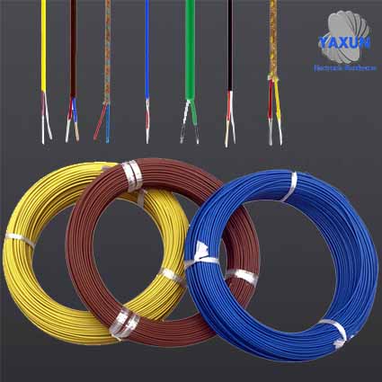
Twisted pair (TP) is the most commonly used transmission medium in integrated wiring projects. It is composed of two copper wires with an insulating protective layer. The two insulated copper wires are twisted together at a certain density, and the radio waves radiated by each wire during transmission will be offset by the radio waves emitted by the other wire, effectively reducing signal interference.
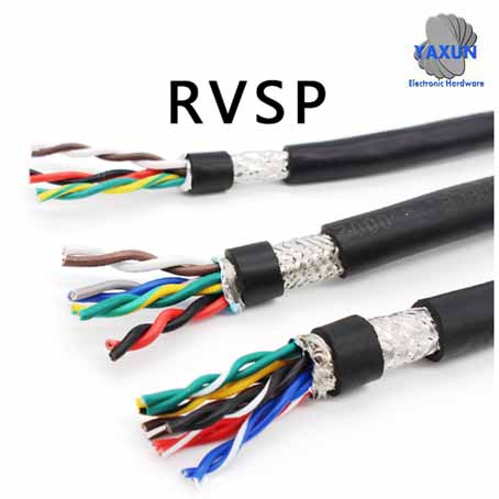
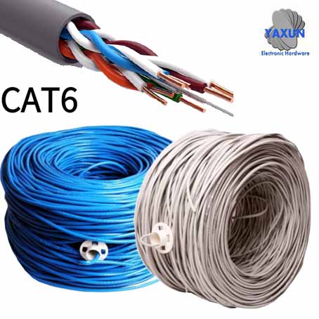
Twisted-pair wire is generally formed by two 22-26 gauge insulated copper wires twisted with each other, and the name "twisted pair" is also derived from this. In actual use, the twisted-pair wire is wrapped in an insulated cable sleeve by multiple pairs of twisted-pair wires. If one or more pairs of twisted pairs are placed in an insulating sleeve, it becomes a multi-pair cable, but in daily life, the "twisted pair cable" is generally directly called "twisted pair".
Compared with other transmission media, twisted pair cables are subject to certain restrictions in terms of transmission distance, channel width and data transmission speed, but the price is relatively low.
Principle of twisted pair
Twisted pair wire is formed by twisting a pair of mutually insulated wires. In this way, it can not only resist a part of electromagnetic wave interference from the outside, but also reduce the mutual interference between multiple pairs of twisted wires. Two insulated wires are twisted together, and the interference signal acts on the two wires that are twisted together (this interference signal is called a common mode signal). In the differential circuit of the received signal, the common mode signal can be eliminated to extract the useful signal (differential mode signal).The function of the twisted pair is to make the noise (in the professional field, the useless signal is called noise) generated by the external interference on the two wires the same, so that the subsequent differential circuit can extract the useful signal. The differential circuit is a subtraction circuit in which the in-phase signals (common mode signals) at the two input ends cancel each other out (m-n), and the inverted signal is equivalent to x-(-y) and is enhanced. Theoretically, m=n and x=y in twisted pair and differential circuits are equivalent to the interference signal is completely eliminated and the useful signal is doubled, but there are certain differences in actual operation.
In a cable sleeve, different wire pairs have different twist lengths. Generally speaking, the twisting length is within 38.1mm ~ 140mm, twisted in a counterclockwise direction, and the twisting length of the adjacent wire pair is within 12.7mm. The length of one twisting cycle of a twisted pair is called the pitch. The smaller the pitch (the denser the twisted wire), the stronger the anti-interference ability.
Classification of twisted pair
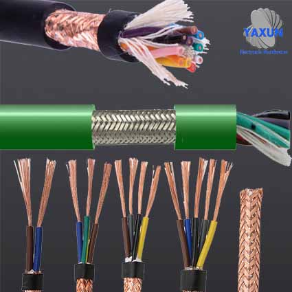
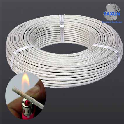
According to whether there is a shielding layer, twisted pair cables are divided into shielded twisted pair (STP) and unshielded twisted pair (UTP).Shielded twisted pair is a metal shielding layer between the twisted pair and the outer insulating sheath. Shielded twisted pair is divided into STP and FTP. STP means that each line has its own shielding layer, while FTP only works when the entire cable has a shielding device and both ends are properly grounded. Therefore, the entire system is required to be shielded devices, including cables, information points, crystal heads, and patch panels. At the same time, the building needs to have a good grounding system. The shielding layer can reduce radiation, prevent information from being eavesdropped on, and prevent the entry of external electromagnetic interference, so that the shielded twisted pair has a higher transmission rate than the similar unshielded twisted pair. However, in actual construction, it is difficult to perfectly ground all of them, so that the shielding layer itself becomes the largest source of interference, resulting in performance that is far inferior to unshielded twisted pair cables. Therefore, unless there are special needs, usually only unshielded twisted pairs are used in the integrated wiring system.
Unshielded twisted pair (abbreviated as UTP) is a data transmission line composed of four pairs of transmission lines of different colors, which are widely used in Ethernet circuits and telephone lines. Unshielded twisted pair cable has the following advantages:
1. No shielding jacket, small diameter, saving space occupied, and low cost;
2. Light weight, easy to bend and easy to install;
3. Minimize or eliminate crosstalk;
4. It is flame retardant;
5. With independence and flexibility, it is suitable for structured integrated wiring. Therefore, in the integrated wiring system, unshielded twisted pair is widely used.
Classification according to frequency and signal-to-noise ratio
Common twisted-pair cables are Category 3, Category 5, Category 5 Super, and Category 6 cables. The former has a thin wire diameter and the latter has a thick wire diameter. The specific models are as follows:1) Category 1 cable (CAT2): The maximum frequency bandwidth of the cable is 750kHZ, which is used for alarm systems or only for voice transmission (a type of standard is mainly used for telephone cables before the early 1980s), not for data transmission.
2) Category 2 cable (CAT2): The maximum frequency bandwidth of the cable is 1MHZ, which is used for voice transmission and data transmission with a maximum transmission rate of 4Mbps. It is common in the old token network that uses the 4MBPS standard token passing protocol.
3) Three types of cables (CAT3): Refers to the cable specified in the ANSI and EIA/TIA568 standards. The transmission frequency of the cable is 16MHz and the highest transmission rate is 10Mbps (10Mbit/s). Mainly used in voice, 10Mbit/s Ethernet (10BASE-T) and 4Mbit/s token ring, the maximum length of the network segment is 100m, the use of RJ connectors, has faded out of the market.
4) Four types of cables (CAT4): The transmission frequency of this type of cable is 20MHz, which is used for voice transmission and data transmission with a maximum transmission rate of 16Mbps (referring to 16Mbit/s token ring). Mainly used for token-based LAN and 10BASE-T/100BASE-T. The maximum length of the network segment is 100m, and the connector in the form of RJ is not widely used.
5) Category 5 cable (CAT5): This type of cable increases the winding density and coats a high-quality insulating material. The maximum frequency bandwidth of the cable is 100MHz, and the maximum transmission rate is 100Mbps. Used for voice transmission and data transmission with a maximum transmission rate of 100Mbps, mainly used in 100BASE-T and 1000BASE-T networks. The maximum length of the network segment is 100m, and the connector in the form of RJ is adopted. This is the most commonly used Ethernet cables. In twisted-pair cables, different pairs have different lay lengths. Generally, the lay period of 4 pairs of twisted pairs is within 38.1mm in length, twisted in a counterclockwise direction, and the twisted length of a pair of wires is within 12.7mm.
6) Super Category 5 cable (CAT5e): Super Category 5 cable has low attenuation, less crosstalk, higher attenuation to crosstalk ratio (ACR) and signal-to-noise ratio (SNR), smaller delay error, and performance is greatly improved. Super Category 5 cable is mainly used for Gigabit Ethernet (1000Mbps).
7) Category 6 cable (CAT6): The transmission frequency of this type of cable is 1MHz~250MHz, and the comprehensive attenuation crosstalk ratio (PS-ACR) of Category 6 wiring system should have a large margin at 200MHz. It provides 2 times the bandwidth of Super Category 5. The transmission performance of Category 6 cabling is much higher than that of the Super Category 5 standard, and is most suitable for applications with a transmission rate higher than 1Gbps. An important difference between Category 6 and Category 5 is:
Improved crosstalk and return loss performance. For a new generation of full-duplex high-speed network applications, excellent return loss performance is extremely important. The basic link model is cancelled in the six types of standards, and the wiring standard adopts a star topology. The required wiring distance is:
The length of the permanent link cannot exceed 90m, and the length of the channel cannot exceed 100m.
8) Super Category 6 or 6A cable (CAT6A): The transmission bandwidth of this type of product is between Category 6 and Category 7, the transmission frequency is 500MHz, the transmission speed is 10Gbps, and the standard outer diameter is 6mm. Like the seven types of products, the country has not issued a formal testing standard, but there are such products in the industry, and each manufacturer announces a test value.
9) Category 7 cable (CAT7): The transmission frequency is 60+0MHz, the transmission speed is 10Gbps, the standard outer diameter of single wire is 8mm, and the standard outer diameter of multi-core wire is 6mm.
The larger the type number, the newer the version, the more advanced the technology, the faster the bandwidth, and of course the more expensive it is. These different types of twisted pair marking methods are stipulated in this way. If it is a standard type, it is marked as CATx. For example, the commonly used Category 5 and Category 6 wires are marked as CAT 5 and CAT 6 on the outer skin of the wire. If it is an improved version, it will be marked as xe. For example, the super five-category line is marked as 5e (the letters are lowercase, not uppercase).
Regardless of the line, the attenuation increases with the increase in frequency. When designing the wiring, consider that the attenuated signal should also have a large enough amplitude so that it can be correctly detected at the receiving end under the condition of noise interference. How high a rate (Mb/s) the twisted pair can transmit data also has a great relationship with the encoding method of the digital signal.
Sequence standard
In North America, the three most influential international cabling organizations are as follows. ANSI (American National Standards Institute) TIA (Telecommunication Industry Association) EIA (Electronic Industries Alliance). Since the two organizations TIA and ISO often coordinate in the development of standards, the difference between the standards promulgated by TIA and ISO is not very large. In North America, and even the world, the most widely used twisted pair standards are ANSI/EIA/TIA-568A and ANSI/EIA/TIA-568B (actually ANSI/EIA/TIA-568B.1, referred to as T568B). The main difference between these two standards is the difference in core wire sequence:The line sequence definition of EIA/TIA 568A is green and white, green, orange and white, blue, blue and white, orange, brown and white, and brown. The label is shown in the following table:
The line sequence definitions of EIA/TIA 568A are: green and white, green, orange and white, blue, blue and white, orange, brown and white, and brown. The labels are shown in the following table:
|
green and white
|
green
|
orange and white
|
blue
|
blue and white
|
orange
|
brown and white
|
brown
|
|
1
|
2
|
3
|
4
|
5
|
6
|
7
|
8
|
The line sequence definition of EIA/TIA 568B is as follows: orange white, orange, green white, blue, blue white, green, brown white, brown, and its labels are shown in the following table:
|
orange and white
|
orange
|
green and white
|
blue
|
blue and white
|
green
|
orange and white
|
brown
|
|
1
|
2
|
3
|
4
|
5
|
6
|
7
|
8
|
Production steps
The following introduces the most basic method of making straight-through Category 5 cables. The manufacturing methods of other types of network cables are similar, the only difference is that the jumper method is different.step 1: Use a twisted pair network cable pliers (of course, you can also use other cutting tools) to cut one end of the category 5 twisted pair (it is better to cut a piece of network cable that meets the wiring length requirements). Then insert the trimmed end into the gap of the network cable pliers for wire stripping, and make sure that the network cable cannot be bent.
Step 2: Hold the crimping pliers slightly and rotate it slowly (no need to worry about damaging the skin of the core wire inside the network cable, because there is a certain distance between the two stripping blades, which is usually the diameter of the 4 pairs of core wires inside). Let the knife cut the protective rubber of the twisted pair and pull off the rubber. Of course, you can also use a special wire stripping tool to peel off the protective rubber. Note: The stripping length should usually be exactly the length of the crystal head, which can effectively avoid the trouble caused by too long or too short stripping. Too long stripping is unsightly. On the other hand, because the network cable cannot be jammed by the crystal head, it is easy to loosen; The stripped wire is too short, because of the presence of the outer skin, it is too thick to be inserted into the bottom of the crystal head completely, causing the plug pins of the crystal head to not be in good contact with the core wire of the network cable.
Step 3: After stripping the skin, you can see the 4 pairs of 8 core wires of the twisted-pair network cable, and you can see that the color of each pair is different. The two core wires of each pair are composed of a core wire dyed in the corresponding color plus a white and white core wire dyed only a little in the corresponding color. The colors of the four full-color core wires are: brown, orange, green, and blue.
Step 4: Untie each pair of cables that are entangled with each other one by one. After untying, arrange and straighten out several sets of cables in sequence according to the rules. When arranging, care should be taken to avoid excessive winding and overlap of the lines. After arranging and straightening the cables in order, the cables will be bent to a certain extent because they were entangled with each other before. The cables should be pulled as straight as possible and kept flat. The method of pulling the cable straight is also very simple: grasp the cable with both hands and then apply force in two opposite directions and pull it up and down.
Step 5: After arranging the cables in sequence and straightening and pressing them, you should check them carefully, and then use the cutting edge of the crimping pliers to cut the cable tops neatly.
Step 6: Insert the organized cable into the crystal head. It should be noted that the side of the crystal head with the molded spring leaf should be downward and the side with the pins should be upward, so that the end with the pins points away from you, and the end with the square hole faces you. At this time, the leftmost foot is the 1st foot, the rightmost foot is the 8th foot, and the rest are arranged in order. When inserting, you need to pay attention to slowly and forcefully insert the 8 cables along the 8 wire grooves in the IU-45 head at the same time, and insert them to the top of the wire groove. Note: When cutting, it should be inserted horizontally, otherwise the cable length will affect the normal contact between the cable and the crystal head. If you have stripped off the protective layer too much before, you can cut the too long thin wire here, leaving the part of the outer protective layer about 15mm, which is just enough to insert the thin wires into their respective wire slots. If this section is left too long, it will increase crosstalk because the cables are no longer twisted. Secondly, because the crystal head cannot press the sheath, the cable may fall out of the crystal head, resulting in poor contact or even interruption of the line. Before the final step of crimping, you can check from the top of the crystal head to see if each set of cables is tightly pressed against the end of the crystal head.
Step 7: Pressure line. Before the last step of crimping, you can check from the top of the crystal head to see if each set of cables is tightly pressed against the end of the crystal head. After confirming that it is correct, you can insert the crystal head into the 8P slot of the crimping tool to crimp. After inserting the crystal head, firmly grasp the wire pliers, if you are not strong enough, you can use both hands to press it together. In this pressing process, all the pins protruding from the crystal head are pressed into the crystal head, and a slight "pop" is heard after applying force.
Step 8: After crimping, the pins of the network crystal head protruding outside are all pressed into the crystal parallel head, and the plastic buckle at the lower part of the network crystal head is also pressed against the gray protective layer of the network cable. At this point, the network crystal head is finished.
Performance indicators
For twisted-pair cables, users are most concerned about several indicators that characterize its performance. These indicators include attenuation, near-end crosstalk, impedance characteristics, distributed capacitance, DC resistance, etc.1. Attenuation
Attenuation is a measure of signal loss along the link. Attenuation is related to the length of the cable. As the length increases, the signal attenuation also increases. Attenuation uses "db" as the unit, which represents the ratio of the signal strength from the source transmitting end to the receiving end. Since attenuation varies with frequency, the attenuation at all frequencies within the application range should be measured.
2. Near-end crosstalk
Crosstalk is divided into near-end crosstalk and far-end crosstalk (FEXT). The tester mainly measures NEXT. Because of the line loss, the magnitude of FEXT has less influence. Near-end crosstalk (NEXT) loss is the measurement of signal coupling from one pair of wires to another in an unshielded twisted pair link. For unshielded twisted pair links, NEXT is a key performance index, and it is also the most difficult index to accurately measure. As the signal frequency increases, its measurement difficulty will increase. NEXT does not mean the crosstalk value generated at the near end point, it just means the crosstalk value measured at the near end point. This value will vary with the length of the cable, the longer the cable, the smaller its value becomes. At the same time, the signal at the transmitting end will be attenuated, and the crosstalk to other wire pairs will be relatively small. Experiments have proved that only the NEXT measured within 40 meters is more real. If the other end is an information socket farther than 40 meters, then it will produce a certain degree of crosstalk, but the tester may not be able to measure this crosstalk value. Therefore, it is best to perform NEXT measurements at both endpoints. Most testers are equipped with corresponding equipment so that the NEXT value at both ends can be measured at one end of the link. Refer to the following table for the results of the NEXT test:
|
Frequency (MHz)
|
Maximum attenuation (20℃)
|
|||||
|
Channel (100 meters)
|
Link (90 meters)
|
|||||
|
Media category
|
Category 3
|
Category 4
|
Category 5
|
Category 3
|
Category 4
|
Category 5
|
|
1
|
4.2
|
2.6
|
2.5
|
3.2
|
2.2
|
2.1
|
|
4
|
7.3
|
4.8
|
4.5
|
6.1
|
4.3
|
4.0
|
|
8
|
10.2
|
6.7
|
6.3
|
8.8
|
6
|
5.7
|
|
10
|
11.5
|
7.5
|
7.0
|
10
|
6.8
|
6.3
|
|
16
|
14.9
|
9.9
|
9.2
|
13.2
|
8.8
|
8.2
|
|
20
|
11
|
10.3
|
9.9
|
9.2
|
||
|
25
|
11.4
|
10.3
|
||||
|
31.25
|
12.8
|
11.5
|
||||
|
62.5
|
18.5
|
16.7
|
||||
|
100
|
24
|
21.6
|
||||
|
Frequency (MHz)
|
Minimum NEXT
|
|||||
|
Channel (100 meters)
|
Link (90 meters)
|
|||||
|
Media category
|
Category 3
|
Category 4
|
Category 5
|
Category 3
|
Category 4
|
Category 5
|
|
1
|
39.1
|
53.3
|
60.0
|
40.1
|
54.7
|
60.0
|
|
4
|
29.3
|
43.3
|
50.6
|
30.7
|
45.1
|
51.8
|
|
8
|
24.3
|
38.2
|
45.6
|
25.9
|
40.2
|
47.1
|
|
10
|
22.7
|
36.6
|
44.0
|
24.3
|
38.6
|
45.5
|
|
16
|
19.3
|
33.1
|
40.6
|
21
|
35.3
|
42.3
|
|
20
|
31.4
|
39.0
|
33.7
|
40.7
|
||
|
25
|
37.4
|
39.1
|
||||
|
31.25
|
35.7
|
37.6
|
||||
|
62.5
|
30.6
|
32.7
|
||||
|
100
|
27.1
|
29.3
|
||||
3. DC resistance
The DC loop resistance consumes part of the signal and converts it into heat. It refers to the sum of the resistance of a pair of wires. The DC resistance of the 11801 twisted pair must not be greater than 19.2 ohms. The difference between each pair should not be too large (less than 0.1 ohm), otherwise it indicates poor contact, and the connection point must be checked.
4. Characteristic impedance
Different from the loop DC resistance, the characteristic impedance includes resistance, inductance impedance and capacitance impedance with a frequency of 1 to 100 MHz. It is related to the distance between a pair of wires and the electrical performance of the insulator. Various cables have different characteristic impedances, while twisted-pair cables have 100 ohms, 120 ohms and 150 ohms.
5. Attenuation crosstalk ratio (ACR)
In some frequency ranges, the proportional relationship between crosstalk and attenuation is another important parameter that reflects cable performance. ACR is sometimes also expressed in terms of signal-to-noise ratio (SNR: Signal-Noice ratio), which is calculated from the difference between the worst attenuation and the NEXT value. A larger value of ACR indicates stronger anti-interference ability. General system requirements are at least greater than 10 decibels.
6. Cable characteristics
The quality of the communication channel is described by its cable characteristics. SNR is a measure of the strength of the data signal taking into account the interference signal. If the SNR is too low, it will cause the receiver to be unable to distinguish between the data signal and the noise signal when the data signal is received, which will eventually cause data errors. Therefore, in order to limit the data error within a certain range, a minimum acceptable SNR must be defined.