Analysis of loop design method of automobile wiring harness
The wire harness is used as the connection carrier of the automotive electrical functions to realize the circuit connection between the electrical components. The start and end points of each circuit connection constitute the loop in the wiring harness product. It can be said that the wiring harness circuit is the core of the wiring harness product, and the quality of the circuit design of the wiring harness product directly determines the safety and reliability of the vehicle wiring harness. With the increase in the electrification of vehicles, the data of electrical components has increased, the signal interaction between electrical appliances has become closer and closer, and the number of automotive wiring harness circuits has also increased sharply. The wiring harness loop data of general models has reached nearly 1,000.
How to optimize the overall number of loops so many, is the problem faced by automotive wiring harness design.
The existing automotive wiring harness design technical materials mainly provide design guidance for wiring harness design in the selection of wiring harness materials and manufacturing and processing links. However, there is a lack of systematic analysis on the planning and design concept of the wiring harness loop. This article explains the relevant key points of the wiring harness loop design from two aspects of cost and performance, and provides a specific control path, which has a certain guiding effect on the wiring harness loop design.
2. Circuit design method based on wiring harness
The wiring harness loop accounts for about 90% of the wiring harness material cost, including wires and connectors. To control the cost of wiring harness design, we must start with the optimization of wiring harness loop design. Regarding the use of wires, how to use the minimum wire length to realize the loop connection function is the first issue to be considered in loop design. This involves two design elements: The location of electrical components and the selection of wiring harness routing. These two elements are independent and interrelated, and have a significant impact on the use of wire length.
First, it is necessary to determine the connection method of the circuit based on the principle of the components, and then determine the preliminary position of the layout of the components in the vehicle environment, and the selection of the wiring harness layout path is based on the layout of the components. Use the shortest harness length to cover as many parts as possible, which is also the prototype of the vehicle electrical topology.
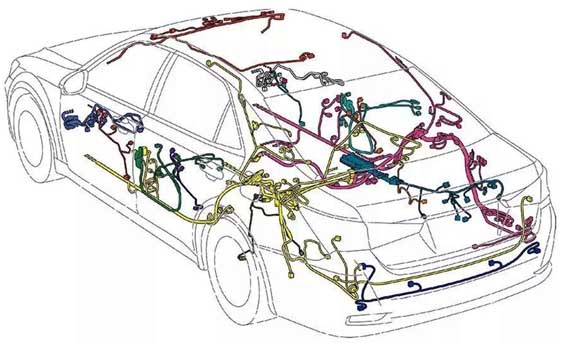
After the complete vehicle topology is built, it needs to be designed and checked. By calculating the specific amount of wire to determine whether the layout of the components and the wiring harness layout path is reasonable (there are currently a large number of software on the market that can achieve this function). The specific method is to compare by adjusting the parts one by one: As shown in Figure 2 and Figure 3, compare the design of different layout positions of the BCM to check the length and quantity of the whole vehicle wire, and then determine which position of the BCM is better.
In this process, there will often be mutual influences: the arrangement and adjustment of component A will affect the selection of the position of component B. Therefore, after determining the influence of each component and wire harness path on the use length of the wire, the first round of preferred solutions will have a greater impact on the length of the wire. On this basis, the topology is rebuilt, and the other secondary solutions are compared and analyzed again, so as to realize the topology design platform with the least wire length.
The perfect topology can ensure that the amount of wires is minimized, and at the same time, for the use of wires. In the traditional design concept, there are clear requirements for the selection of wires. In order to avoid confusion of terminal insertion, more wire colors are often used to distinguish. However, with the continuous improvement of manufacturing level and inspection methods, in fact, the wire color of the wire can be appropriately designed and adjusted, and the circuit function can be realized with the least wire type, which is also a method to reduce the cost of circuit design from a design perspective.
Regarding connectors, how to minimize the use of connectors and reduce the number of switching loops is a key concern in circuit design. Here, wiring harness design engineers need to be transformed into system design engineers, and the design work of reducing the use of connectors and switching circuits needs to be moved to the design and planning of electrical components. There are two main aspects to consider:
On the one hand, the functional circuits of electrical components can be distinguished according to the vehicle configuration. For example, the airbag controller can design the basic functional circuit in the same connector. The high configuration or extended function is arranged in another connector, so that only one connector can be used on the low configuration model, and the electrical circuit function can also be realized.
On the other hand, it can also be planned according to the connection area of the loop. For example, it is also an airbag controller. Some designers will consider designing the function of the chassis in the same connector, and designing the function of connecting the instrument panel in another connector. Such a plan can reduce the mutual transfer of circuits in various regions. This area-based functional loop design is particularly effective for electrical components with more connection pins (such as BCM controllers).
3. Performance-based circuit design method
The wiring harness loop is the core of the circuit connection. The safety and reliability of the circuit connection are requirements that must be met. The wires and connectors in the loop design must follow the requirements of the load and the environment. These contents have been described in detail in other design materials. This article only explains how to ensure the design of the loop performance from the path selection of the loop.
First, the design of the loop must avoid undetectable failure modes. The circuit in which the rear of the fuse is connected in parallel with the relay coil end and the contact end is very common in the design of the whole vehicle circuit. When the relay coil end and the contact end terminal are different, such a design is obviously reasonable, but when the relay coil end and the contact end terminal are the same. With this design, when the terminal is inserted into the relay hole in the wrong position, the current electrical inspection equipment cannot identify such a failure mode.
Therefore, this circuit design method cannot be used in some cases. Of course, the design environment and manufacturing environment faced by different design engineers are different, and the specific failure modes are also different, but the evasion of failure modes in circuit design is the first consideration.
To reduce the wire coupling interference in the loop design, we must first distinguish the interference loop and the sensitive loop. Simply put, inductive load circuits: such as ignition coils, horns, motors, etc. belong to interference circuits. The circuits of images, radar probes, low-power LED lights, and various sensors are sensitive circuits. In the design process, the interference loop and the sensitive loop need to be arranged separately. Experiments show that increasing the wire spacing can reduce high-frequency interference. In the case where the distinction cannot be made, functional tests must be performed by wire injection interference to determine the correct circuit design.
At the same time, in order to reduce the influence of harness radiation and coupling, the circuit loop area and harness length should be reduced as much as possible. In the design of the entire automobile, it is necessary to minimize the loop area of the wiring harness, especially the power line and the ground wire, and the wiring harness in the loop is required to run in parallel. At the same time, try to fix it as close to the metal body as possible to reduce the loop area, and the separation distance of wiring should not exceed 50cm.
In addition to the consideration of the layout of interference loops and sensitive loops, the anti-interference components twisted pair and shielded wires used on the wiring harness also need to be paid attention to in the loop design to achieve the shielding expectations: The diameter and length of the two wires of the twisted twisted pair should be the same, and the lay length is preferably 10-20mm. The specific lay length is subject to the test; The shielding layer ground terminal should connect the shielding layer with the shielding shell 360° at the beginning and the end, and the shielding layer and the shielding shell will completely shield the signal line. For the shell of the shielded cable connection component is not a metal structure, you can use metal conductive clips to install the shielding laminate on the metal plate that is reliably connected to the car body, and the shielding effectiveness should reach 60dB.
4. in conclusion
This article analyzes the circuit design method of automobile wiring harness from the aspects of cost and performance, and explains the application of specific methods in combination with work practice. Refining the key points of the wiring harness loop design has guiding significance for the wiring harness design engineer in the loop design process.


