Fuse box wiring harness group for relay
The relay control control circuit is usually represented by the schematic diagram, layout diagram and wiring harness diagram.
1. Wiring schematic diagram
The circuit diagram of the wiring harness is based on the requirements of the electrical control system for the motion form of the production machinery, and adopts the electrical graphic symbols and text symbols uniformly prescribed by the country. According to the working sequence of electrical equipment and electrical appliances, all the basic components and connection relationships of circuits, equipment or complete sets of equipment are shown in detail. A diagram of a harness without considering its actual location.
The wiring harness circuit diagram can fully express the purpose, function and working principle of electrical equipment and electrical appliances, and is the theoretical basis for electrical circuit installation, debugging and maintenance.
The following principles should be followed when drawing the schematic diagram of the wiring harness:
(1) The circuit diagram is generally divided into three parts: power supply circuit, main circuit and auxiliary circuit wiring harness. The wiring harness diagram of the circuit shown in Figure 1.
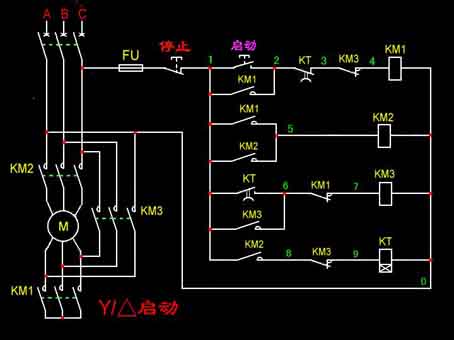
Figure 1, Schematic diagram of jog control
In Figure 1, in accordance with the drawing principles of the circuit diagram, the three-phase AC power lines L1, L2, L3 are drawn horizontally at the top of the figure in turn, and the power switch QS is drawn horizontally; The main circuit composed of the fuse FU1, the 3 pairs of main contacts of the contactor KM and the motor M and the vertical power line are drawn on the left side of the figure; The control circuit composed of the start button SB and the coil of the contactor KM is connected across the two power lines Ll and L2, and is drawn vertically on the right side of the main circuit; And the coil of the energy-consuming element KM is connected to the lower power line U and drawn below the circuit, and the start button SB is drawn between the KM coil and the upper power line Ll. The contactor KM in the figure uses a separate representation. The 3 pairs of main contacts are drawn in the main circuit, and the coils are drawn in the control circuit. To indicate that they are the same electrical appliance, the same text symbol KM is marked next to their graphic symbols. The lines are numbered at each contact according to regulations.
(2) In the circuit diagram, the contact position of each electrical appliance is drawn according to the normal position when the circuit is not energized or the electrical appliance is not subjected to external force. When analyzing the principle, we should start from the normal position of the contact.
(3) The actual outline drawing of each electrical component is not drawn in the circuit diagram, but the electrical graphic symbols specified by the state are used to draw it.
(4) In the circuit diagram, the components of the same electrical appliance are not drawn together according to their actual positions, but are drawn in different circuits according to their roles in the circuit. But their actions are related to each other, therefore, the same text symbols must be marked. If there are many identical appliances in the picture, different Arabic numerals need to be added after the text symbols of the appliances to show the difference, such as KM1, KM2, etc.
(5) When drawing circuit diagrams, try to reduce lines and avoid lines crossing. For cross-wire connection points with direct electrical connection, use small black dots to indicate; No small black dots are drawn on cross wires without direct electrical connection.
(6) The circuit diagram adopts the circuit numbering method, which means that each contact in the circuit is numbered with letters or numbers.

1. Wiring schematic diagram
The circuit diagram of the wiring harness is based on the requirements of the electrical control system for the motion form of the production machinery, and adopts the electrical graphic symbols and text symbols uniformly prescribed by the country. According to the working sequence of electrical equipment and electrical appliances, all the basic components and connection relationships of circuits, equipment or complete sets of equipment are shown in detail. A diagram of a harness without considering its actual location.
The wiring harness circuit diagram can fully express the purpose, function and working principle of electrical equipment and electrical appliances, and is the theoretical basis for electrical circuit installation, debugging and maintenance.
The following principles should be followed when drawing the schematic diagram of the wiring harness:
(1) The circuit diagram is generally divided into three parts: power supply circuit, main circuit and auxiliary circuit wiring harness. The wiring harness diagram of the circuit shown in Figure 1.
Figure 1, Schematic diagram of jog control
(2) In the circuit diagram, the contact position of each electrical appliance is drawn according to the normal position when the circuit is not energized or the electrical appliance is not subjected to external force. When analyzing the principle, we should start from the normal position of the contact.
(3) The actual outline drawing of each electrical component is not drawn in the circuit diagram, but the electrical graphic symbols specified by the state are used to draw it.
(4) In the circuit diagram, the components of the same electrical appliance are not drawn together according to their actual positions, but are drawn in different circuits according to their roles in the circuit. But their actions are related to each other, therefore, the same text symbols must be marked. If there are many identical appliances in the picture, different Arabic numerals need to be added after the text symbols of the appliances to show the difference, such as KM1, KM2, etc.
(5) When drawing circuit diagrams, try to reduce lines and avoid lines crossing. For cross-wire connection points with direct electrical connection, use small black dots to indicate; No small black dots are drawn on cross wires without direct electrical connection.
(6) The circuit diagram adopts the circuit numbering method, which means that each contact in the circuit is numbered with letters or numbers.


