How to calculate and select the correct wires and cables
Cable cross-section verification
(1) Select the cable according to the voltage: select the cable according to the first of the above principles.
(2) Choose the cable section according to the economic current density: the calculation method is the same as that of the wire section.
(3) Check the cable cross-section Iux≥Izmax according to the maximum long-term load current of the line
In the formula: Iux——the allowable load current of the cable (A);
Izmax——The long-term maximum load current (A) in the cable.
This selection method is the most commonly used in our daily work. Usually the working current of the line is calculated first, and then the maximum working current of the line should not be greater than the allowable current carrying capacity of the cable. The allowable long-term working current of the cable is shown in Table 1.
We often encounter this situation in actual work. As the load increases, the load current increases, the original cable current carrying capacity is insufficient, and the overload current runs. In order to increase the capacity, considering the normal operation of the original cable, it is difficult and uneconomical to re-lay the cable. We often use double-wire or even triple-wire method.
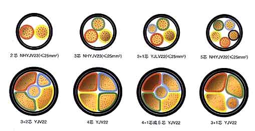
In the selection of combined cables, many people think that the smaller the cable cross-section, the more economical and the more reasonable it is, as long as the current-carrying capacity requirements are met. Is this actually the case?
On January 3, 2006, the main cable from the transformer No. 1 to the power distribution room burst. Two of the original 185mm four-core aluminum-core cables burst one. In order to restore the power supply in time, the work area kept another good cable and used two 120mm four-core aluminum cables for power supply. After 10 months of operation, the main cable burst again on November 15, 2006. After inspection, it was found that the 185mm cable burst caused the accident.
Why did this accident happen? According to Table 1, we can conclude that the safe current carrying capacity of the three cables used together is 668A, and the maximum load current measured by the clamp-type ammeter is only 500A in the living area. According to the principle of Iux≥Izmax, this operation should be safe and reliable. However, we ignore that the cable has resistance, because when multiple parallel cables are connected, the contact resistance is different at the connection, and this contact resistance is often comparable to the resistance of the cable itself. As a result, the current distribution of the multi-parallel cable will be unbalanced. The current distribution of the multi-parallel cable is related to the impedance of the cable.
Rough calculation of copper wire interface: S=IL/54.4U (S wire cross-sectional area in millimeters)
Rough calculation of aluminum wire interface: S=IL/34U
Resistance calculation
The DC standard resistance of the cable can be calculated according to the following formula:
R20=ρ20(1+K1)(1+K2)/∏/4×dn×10
In the formula: R20——The standard resistance of the branch current of the cable at 20℃ (Ω/km)
ρ20——Resistivity of wire (at 20℃) (Ω*mm/km)
d——The diameter of each core wire (mm)
n——Number of core wires;
K1-core wire twist rate, about 0.02-0.03;
K2——The twist rate of the multi-core cable, about 0.01-0.02.
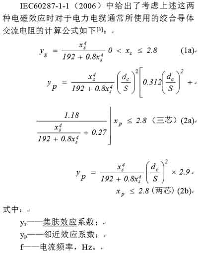
The actual AC resistance per kilometer of cable at any temperature is:
R1=R20 (1+a1) (1+K3)
In the formula: a1——The temperature coefficient of resistance at t℃;
K3—— Taking into account the coefficient of skin effect and proximity effect, 0.01 when the cross-sectional area is less than 250mm;
0.23-0.26 at 1000 mm.
Calculation of capacitance
C=0.056Nεs/G
In the formula: C—— Cable capacitance (uF/km)
εs-relative permittivity (standard is 3.5-3.7)
N—— The number of hearts of the multi-core cable;
G—— Shape factor.
For underground cables for power distribution, when the conductor cross-section is round, and the loss of armor and lead-cladding is neglected, the inductance calculation method of each cable is the same as that of the wire.
L=0.4605㏒Dj/r+0.05u
LN=0.4605㏒DN/rN
In the formula: L—— the inductance of each phase wire (mH/km)
LN—— the inductance of the neutral wire (mH/km);
DN——The geometric distance between the phase line and the neutral line (cm);
rN—— the radius of the neutral line (cm);
DAN, DBN, DCN-the center distance between each phase line to the neutral line (cm).


